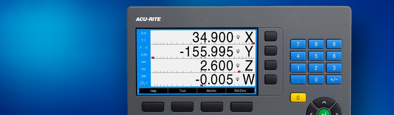
DRO 300 Digital Readout
The most complete digital readout system in the machine tool marketplace, the DRO300 has full part program capability, 99 tool offsets and multiple DRO displays along with standard input/output capability and edgefinder probe support all on an easy to read 7-inch color display. Designed and manufactured in the USA, ACU-RITE readouts are the first choice of machine tool builders and users alike.
DRO300 support
Installation instructions (in English, French, Spanish)
Want More Information?
Enter your contact information and we'll get back to you as soon as possible.

Milling-specific features
- Bolthole pattern calculations with graphics (full and partial circles/linear patterns)
- Centerline calculation enables you to establish workpiece zero and midpoints
- Edge finder input
- I/O (option)

Turning-specific features
- Lock axis feature
- Instant radius/diameter conversion
- Taper calculator
- CSS (option)
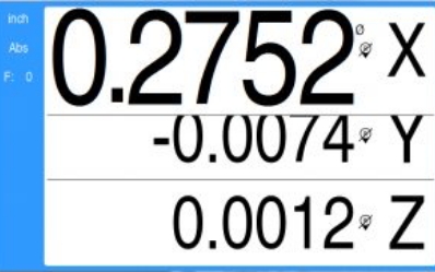
Dynamic zoom
The currently moving axis can be geographically highlighted. In “dynamic zoom” mode, the position value is zoomed to its maximum size depending on the number of digits. This greatly improves legibility—especially from a great distance. Click here to see Dynamic Zoom in action.

Installation guide
When you switch on the digital readout for the first time, the DRO300 supports you with an installation guide. You are led step by step through the most important settings until the device is ready for operation.

Day/night switching
Depending on the ambient-light conditions at the machine, you can switch the screen of the DRO300 to a light or dark background.
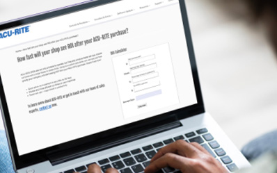
Curious about ROI?
With our DRO ROI calculator, you can input your shop’s characteristics and find out how quickly a DRO can pay you back.
International documentation
Visit our Manuals & Flyers page and scroll to the bottom for international documentation.
Frequently Asked Questions
Can the DRO300 be used in EDM machines?
Yes, with an IOB 610 the DRO300 can use six inputs and ten outputs, making them suitable for EDM functionality.
How many axes can the DRO300 work with?
Standard DRO300 readouts work with up to four axes. The IB2X option allows for input of two additional axes, up to six, making the DRO300 readouts a fit for large machine tools.
Can the DRO300 be used with an Edge Finder or touch probe?
Yes, with the help of the IOB 610, DRO300 includes input for touch probes and ACU-RITE Edge Finder with switching signal or contact triggering.
Specifications
| Application | Milling, turning, grinding, boring, EDM and general purpose |
| Axes | 2, 3, and 4 from A to Z and Z0 |
| Encoder Inputs | TTL |
| Display Step |
|
| Display |
|
| Status Display |
|
| Axis Display | Standard |
| Common Functions |
|
| Turning Specific Functions |
|
| Milling Specific Functions |
|
| Cycles | Oblique line, circular arcs; only for milling, drilling, boring:circular and linear hole patterns |
| Error Compensation |
|
| Data Interface | USB 2.0 type C
|
| Switching I/O |
|
| Options |
|
| Electrical Requirements | AC 100 V to 240 V (±10 %), 50 Hz to 60 Hz (±5 %), ≤ 33 W |
| Operating Temperature | 0° to 45º C (32º to 113º F) |
| Protection EN60529 | IP 40, Front Panel IP 54 |
| Weight | ~1.9 kg |